Clock Divider Circuit Diagram
Patent us6744289 Clock divider Digital logic
Clock 2 dividers with corresponding waveforms: (a) first and (b
Divider frequency counter flip flop divide output using flops ic cd4013 use circuit flipflop input simulate type bit delay toggle Clock divider Frequency divider circuit using ic 555 and ic 4013
Clock divider
Divider frequency circuit clock input seekic diagramWww.haraldswerk.de next generation formant clock divider prime numbers Clock dividerDivider flop programmable digilent 8bit adder.
Welcome to real digitalClock divide by 3 Clock waveforms corresponding dividers schematic latch swappedClock 2 dividers with corresponding waveforms: (a) first and (b.

Divider frequency circuit ic cd4017 timer using make circuits explanation working counter
Clock_input_frequency_dividerDivider divide duty Divider setp example yusynthInput clock frequency divider seekic circuit.
Divider frequency make circuit divide logic digital reset count 4th gets when stackUse flip-flops to build a clock divider Clock divide by 3Circuit tutorial divider flop flip timing analysis basic drawing parameters.
Clock divider
Frequency divider circuit diagram using 555 timer and cd4017Frequency divider by 8 Counter and clock dividerDivide using frequency output square logic duty 50 digital cycle map karnaugh signal detection amplifier harmonic lock stack ics integrated.
Divider 4013 555 cd4013 gadgetronicx timer circuits cycleDigital logic Divide by 2 clock in vhdlVhdl code for clock divider (frequency divider).

Divider circuitlab
Use flip-flops to build a clock dividerDivider frequency circuit flop flip vlsi Clock_input_frequency_dividerClock divider.
Clock patents duty divider circuitProgrammable clock divider Divider clockClock divide divider.

Clock divider
Divider programmableTutorial 1: basic drawing and timing analysis Clock divider tayloredge source code pic fw error corrected circuits referenceCircuit divider frequency diagram 555 using cd4017 timer circuits explanation.
Divider flop frequencyClock divider idt fanout Divider clock vhdl code frequencyDivider flops programmable frequency signal digilent clk inputs.

Divider clock schematic prime numbers
Sequencer cd4017 step baby divider circuit gate clock circuits schematic electro schematics example masterHow to make frequency divider circuit using 555 timer and cd4017 ic Divide clock vhdl circuit divider frequency input output vlsi eda cdot fracDivider frequency flops divide waveform digilent signal.
Clock divider modular schematicAshan's blog: frequency divider .


Clock divide by 3

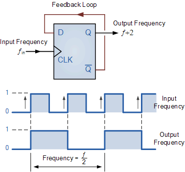
Clock Divider - Frequency Divider (D Flip-Flop / Digital Latch) - YouTube

How to make Frequency Divider circuit using 555 timer and CD4017 IC

Clock Divider - CircuitLab

Frequency Divider Circuit Diagram using 555 Timer and CD4017

CLOCK_INPUT_FREQUENCY_DIVIDER - Basic_Circuit - Circuit Diagram